PLC? What’s that?!
Posted on 01 August, 2021
Hello there, my fellow logical control freaks wannabe!
Guess you are here to learn more about the wonders of PLC- the short abbreviation of Programmable Logic Controller. PLC has evolved tremendously and now an important integral part of the control system.
So, what is PLC really? Basically, PLC is a combination of software and hardware. It acts as the brain of a system for automation control. Think of it as a digital computer which can be programmed for any purpose and in almost every sector (really!) It uses a programmable memory to store instructions and implement specific functions such as sequence, logics, timing, calculation and arithmetic operations to control machines and processes.
What makes PLC so much more relevant now with the pandemic and the way we work is that PLC CAN be executed AUTOMATICALLY and accurately. It can perform precise operations within the shortest time while centralising many components for controlling devices.
Now that I have your attention, lets move on to the more technical aspects of a PLC system!
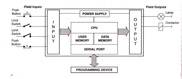
The block diagram of PLC consists of different components. Each component usually serves its specific function and operation in the PLC.

Image source: http://plc-solutions.blogspot.com/p/block-diagram-of-plc.html
In short, basically- The input sections convert the field signals supplied by input devices/sensors to logic-level signals that the PLC’s CPU can read and understand.
The Processor Section reads these inputs, processes the signal, and prepares the output signals.
The output section converts the logic level output signals coming from processor to high level signals and used to actuate various output field devices.
The programmer is used to enter the user's program into memory and to monitor the execution of the program.
Now you might be wondering where exactly the programme is stored. Normally, the program is saved in the RAM of the PLC, but as we know RAM can be a risky place to save your program as it will be cleared off when the power is off. But although most PLC have a backup battery, it is always recommended to save your program more permanently in the EEPROM.
Huh whatttt? Okay here we go~
The I/O section practically establishes the interfacing between the physical devices to the digital arena inside the PLC. The main difference between PLC analogue and digital I/O is signal format, followed by signal wiring and processing. The most common connection methods are:
- Hardwire connection with terminals
- Fieldbus network connection
PLC I/O modules also provide electrical isolation between the I/O modules internal electronic components and its terminal connections. Electrical isolation is necessary to protect the PLC I/O modules internal electronic components and is usually done optically with optocouplers.
What you could be more interested in in is the CPU section, which is to perform dedicated task such as program scan and execution. Where there’s the Power Supply, Memory system and Processor.
The power supply basically provides power to the memory system, processor and I/O Modules. PLC usually run on a 24V DC. However, different brands of PLC probably have very different requirements. More importantly, you should also look into the current rating of the PLC as it will directly affect how much work your PLC system can actually do and definitely the size of the power supply as this will adversely affect the overall size of the PLC syse,. There are 3 main types of power supplies: 1. Integrated PLC power supply 2. PLC power supply module 3. Remote PLC power supply
Memory system stores the program for processing buy the CPU and as well the input and output data for processing and execution. The size of the PLC memory will vary depending on the processing power of the CPU. You will find that higher powered PLC models will be equipped with faster CPUs and will have more onboard memory. However, expandable memory do exist which you can find in some PLC controllers when you run out of memory unexpectedly.
Before we move on to programming devices, lets talk communication.
PLCs can communicate to multiple devices by using a communication interface. The communication interface has communication ports which allows cable connection to devices such as other PLCs, remote I/O drops, fieldbus devices, touch screens, programming PCs and servers. Multiple communication interfaces may be required for larger and more complex applications.
The PLC communication interface can exist as either embedded communication ports on the PLC processor or as communication modules. It’s quite common to see both embedded communication ports on the PLC processor and extra communication modules slotted into the rack.
PLC communication ports commonly use either a Serial based communication protocols or Ethernet based communication protocols. Serial communication ports on a PLC usually use D-sub connectors or terminal connectors, while Ethernet communication ports usually use RJ45 connectors.
Serial protocols or otherwise known as “old but gold”, albeit slower and lacking in data bandwidth as compared the today’s ethernet based protocol, are readily available, generally cheaper and still useful in many applications.
Some popular Ethernet based protocols used for PLC communication include Ethernet IP, Profinet, Ethercat, Modbus TCP/IP and BACnet IP. With Serial communication ports, some of the common protocols are DeviceNet, Profibus DP, Modbus RTU, CANopen, BACnet MS/TP, MPI, DirectNet, RS-485, RS-422 and RS-232.
And finally, Programming Device.
Honestly, I usually would advice to go with personal computers as their functionality is really to develop PLC program and then transfer it to the PLC memory, but I do see the convenience of the very interactive handheld programming devices (HHP) especially when you are just starting out. However, do note that they typically have very basic display and are pretty tedious to use. Think of those as your oversized calculators. They can be pretty handy for simple changes or just to execute programmes.
PLC Scan Cycle vs PLC Scan Time
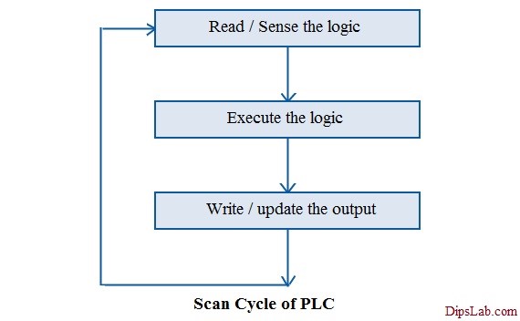
In short, Scan time- This is how PLC program works. The first thing the PLC will do is to check the status of all the inputs. To be more precise, the PLC will take an image of all the inputs and save it in the RAM. And then it will proceed to execute the PLC program and finally update value of outputs. The outputs are actually done in the memory- there will always be a set of numbers that will represent the status of the outputs. And that my friend is the scan cycle, or tldr;

Image source: https://dipslab.com/plc-interview-questions-answers/
Scan time can be very crucial when working with timers and other advance functions in the PLC. The accuracy of the timers will often depend on the length of the scan cycle.
Alright, enough of the good stuff. Let’s get real here with a list of common problems encountered in PLC control systems. PLC can vary so can problems, but we can also classify them into sub-categories.
Here is a guide that I find particularly useful! You are welcome and do check their blog out, they have many very informative reads.
Alright, I think we are good to go for now. If you really want to know how a PLC works, get your hands on the VxWorks documentation because that's what's running the majority of PLCs out there. Or you can check out my other post where I ramble more about understanding and choosing PLCs. Cheers! 😊